All the circuitry in the microprocessor, in fact all the circuitry on the motherboard require a clock signal for operation. The clock signal is the heartbeat of the system. Without a clock signal, the microprocessor and the computer are dead.

The actual oscillations for the clock signal are created by the piezoelectric property of a quartz crystal. By applying a voltage to an electrode on the crystal, it can be made to distort in the electric field. When the electric field is removed, the quartz crystal will generate an electric field as it returns to its previous shape, this can generate a voltage. When a crystal of quartz is properly cut and mounted, it can be made to oscillate with a precise resonant frequency.

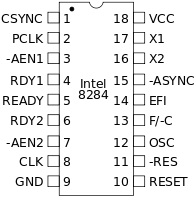
The original PC didn't have on-chip clock generator circuitry, it used the 8284 clock generator chip for generating the clock signal. To configure the 8284, the F/-C pin is tied low and a crystal is connected between the X1 and X2 pins. The 8284 internal circuitry divides the crystal frequency by 3, so if a 15 MHz crystal is connected to the X1 and X2 pins, the output at the CLK pin will be 5 MHz. The CLK pin is connected to the CLK pin of the microprocessor to provide the clock input for the microprocessor.
With the original PC, every time it started it set the system clock to Tuesday, January 1, 1980. The user had to manually enter the proper date and time each time thay started the PC. To avoid this annoyance, the PC AT employed a real-time clock (RTC) chip to keep track of the date and time.
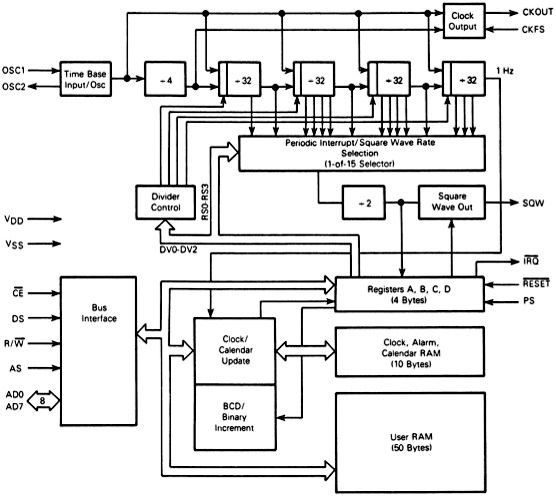
The PC AT originally used the MC146818 chip for the RTC. The RTC chip includes a 128 byte nonvolatile RAM (NVRAM) memory. Both the MC146818 and it's RAM are CMOS (Complementary Metal-Oxide Semiconductor) technology, so they didn't consume much power. Further more, a battery is provided to the chip to keep the clock running even when the power to the system is turned off.

The functional diagram of the MC146818 is shown above. A crystal is connected to the chip OSC1 and OSC2 pins. The RTC can be programmed to generate interrupts at any required intervals of time.
Most modern motherboards have the RTC integrated in the motherboard chipset South Bridge or I/O Controller Hub (ICH) component. Some chips have NVRAM used to store up to 4KB or more. These are designed to store the system configuration information, such as the amount of installed memory, disk drives installed, PnP configuration, passwords, and other information.
More Computer Architecture Articles:
• Basic Computer Architecture
• Microprocessor Counter, Clock, Timer Circuits
• Load Balancing Multiple CPUs in Symmetric Multiprocessing
• Digital Logic Transfer Characteristics
• The Microcontroller's Asynchronous Serial Interface
• CPU Cache Basics
• Multicore Programming
• Capacitors in AC Circuits
• Operating System Boot
• The AMD Athlon 64 X2 Processor

