Capacitors in an AC circuit have a property similar to resistance called reactance except no heat is generated as a result of reactance.

In a purely capacitive circuit,
the capacitor is connected directly
across the AC supply voltage.
As the AC supply voltage increases and decreases, the capacitor charges and discharges with respect to this change. The charging current is directly proportional to the rate of change of the voltage across the capacitor.
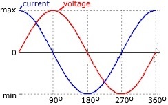
In a purely capacitive circuit
voltage lags current by 90 degrees.
With a sine wave the fastest rate of change is as the supply voltage crosses over from its positive half cycle to its negative half cycle or vice versa at points 0 degrees and 180 degrees along the sine wave. At these points in the cycle the maximum current is flowing through the capacitor.
The slowest rate of change is as the supply voltage sine wave crosses over at its maximum and minimum peak voltage level. At these points in the cycle the minimum current is flowing through the capacitor.
The current flowing through a capacitor in an AC circuit is in opposition to the change of the applied voltage. This AC resistance is known as capacitive reactance. Like resistance, reactance is also measured in Ohm's but it is given the symbol X to distinguish it from a pure resistance. Capacitive reactance is given the symbol Xc.
The amount of capacitive reactance depends on the capacitance of the capacitor in Farads and the frequency of the AC waveform in Hertz. The formula to calculate capacitive reactance is shown below:

Xc in Ohms
F in Hertz
C in Farads
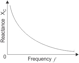
From the formula it can be seen that as either the frequency or the capacitance is increased, the capacitive reactance decreases. As the frequency approaches infinity, the capacitors reactance would reduce to zero acting like a short circuit.
As either the frequency or the capacitance is decreased, the capacitive reactance increases. As the frequency approaches zero or DC, the capacitors reactance would increase up to infinity, acting like an open circuit.
This means that capacitive reactance is "inversely proportional" to frequency for any given value of capacitance.
Impedance of a Series RC Circuit
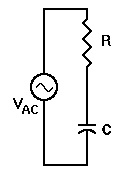
In a series RC circuit, both the resistance (R) and the capacitive reactance (Xc) cause opposition to AC current flow. The total opposition of the circuit is the vector sum of R and Xc, called impedance, and is represented by the letter Z. The units of impedance are ohms.
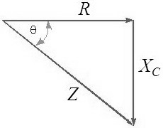
Fortunately, we can use Pythagorean's theorem to calculate impedance.

The phase angle can be calculated with the formula shown below.

The phase angle is the inverse tangent of the capacitive reactance (Xc) divided by the resistance (R). (The range of the inverse tangent is restricted to (-90o, 90o).
Impedance of a Parallel RC Circuit
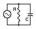
Since the impedance of the resistor is its resistance, we need to know only the impedance of the capacitor. Because it is a parallel circuit, we know that the voltage is the same across all components, its the source voltage.

We know that the current through R is in phase with the voltage across R. But the current through C leads the voltage by 90°. To calculate the total impedance of this circuit we use the capacitative reactance Xc as the equivalent resistance of the capacitor.
As in resistor circuits, the total impedance of a parallel RC circuit is always less than the value of R or XC.
![]()
The phase angle is the inverse tangent of the resistance (R) divided by the capacitive reactance (Xc).
Similar to a series RC circuit, in a parallel RC circuit as either the frequency or the capacitance is increased, the capacitive reactance decreases.
More Computer Architecture Articles:
• How Computer Memory Works
• AMD's Phenom Processor
• Interrupt Request Lines (IRQs)
• Microprocessor Counter, Clock, Timer Circuits
• Getting started with Raspberry Pi
• AMD's Phenom II Processor
• Operating System Memory Paging Hardware Support
• Intel's Core i7 Processors
• Pentium P5 Processor
• Capacitors in DC Circuits

