logic family refers to the way the semiconductors are designed to create gates. The first highly popular logic family, available in 1964, was TTL (Transistor-Transistor Logic). Because of the high power consumption of TTL, in 1968 CMOS (Complementary Metal Oxide Semiconductor) logic was released. Technically you could consider relays and vacuum tubes to logic families, but no-one considers them that.

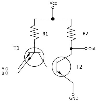
TTL logic gates are made using bipolar junction transistors. Shown above is a simplified implementation of a TTL NAND gate. If the both emitters of T1 are at logic 1, (+5V), there will be very little potential difference between the base and emitter. If however, either one of the inputs is taken to logic 0 (GND), the emitter that is at logic 0 will be at a lower voltage than that supplied to the base by R1. This will make T1 conduct, causing it to saturate and taking its collector to a low potential (less than 0.8V) and since this is also connected to T2 base, T2 will turn off, making its collector voltage rise to near +Vcc (logic 1).

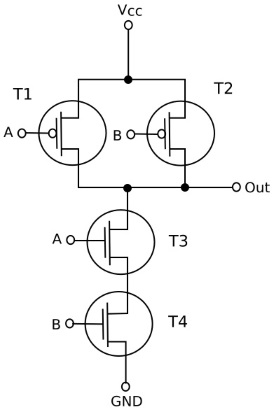
CMOS logic gates use N-channel and P-channel field effect transistors. Shown above is a simplified implementation of a CMOS NAND gate. T1 and T2 are P channel MOSFETs and either of them will be turned on when logic 0 is applied to its gate. T1 and T2 are connected in parallel from Vcc to the output, so switching either of them on will result in a logic 1 at the output. T3 and T4 are N channel MOSFETs and either of them will be turned on when a logic 1 to its gate. T3 and T4 are connected in series between the output and ground so when both are switched on, a logic 0 will appear at the output. The ultimate logic level at the output depends on the on or off state of the combination of all four transistors, and that is controlled by the logic levels applied to the inputs A and B.
Because of high noise immunity and low power dissipation, CMOS transistors are preferred in large scale integrated circuits. Because static electricity can easily destroy the very thin insulating layer between the gate and the channel of the MOSFET transistor, They require special handling and should always be stored in anti static packaging.
There have been many different logic families over the years:
RTL (Resistor-Transistor Logic) is constructed using resistors as an input network and bipolar junction transistors (BJTs) as switching devices.
DTL (Diode-Transistor Logic) uses diodes to perform the logic function, so there is no interaction between different inputs, so a circuit may have a large number of inputs.
ECL (Emitter Coupled Logic) achieves high-speed operation by using a relatively small voltage swing, preventing the transistors from entering the saturation region and avoiding saturation effects.
The 7400 series alone has developed into many different logic families. The 74LS (Low-power Schottky) family consumes only a few mW, but the supply voltage must be very smooth and any unused inputs should be connected to Vcc or they may pick up electrical noise and cause all kinds of erratic signals in a circuit.
The 74HC family is a special version of High-speed CMOS with 74LS TTL compatible inputs so 74HCT can be safely mixed with 74LS in the same system. But again, any unused inputs should be connected to Vcc or they may pick up electrical noise.
The 4000 family is CMOS that can use a supply voltage of 3 to 15 volts and can tolerate small fluctuations of the supply voltage. Again, inputs have very high impedance and unconnected inputs can pick up electrical noise causing the output to rapidly change in an unpredictable way. An output can sink or source only about 10mA with a 9V supply, which is just enough to light an LED.
More Computer Architecture Articles:
• CPU Process Memory Address Binding
• The Computer's Chipset
• Operating System Services
• Virtual Memory and Memory Paging
• Computer Video Display
• Shortest-Job-First CPU Scheduling Algorithm
• Operating System Processes
• Pi-Top kit - Build Your Own Laptop
• Operating System Memory Protection in a Paged Environment
• Electronic Circuits Basics


